10 — The Four Foundries: Deep Dive
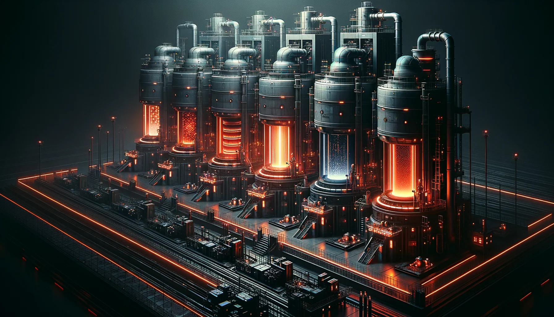
Each of the Four Foundries is engineered for a specific thermodynamic regime and crystal-growth physics. What appears in the overview as four parallel tracks is, in practice, four entirely distinct disciplines — separated by atmosphere, temperature envelope, contamination model, and output geometry. Here they are in full technical detail.
The Vacuum Arc Foundry is the cleanest melt environment in the partner network. A consumable electrode — pre-alloyed to target composition — is suspended above a water-cooled copper crucible inside a hard vacuum chamber held below 10−6 torr. A DC arc is struck between the electrode and the pool below. The electrode tip melts, drips, and recrystallises in a controlled thermal gradient. Dissolved hydrogen, nitrogen, and oxygen are boiled off under vacuum. Macro-segregation — the banding of heavy and light elements as a conventional ingot solidifies — is eliminated by the controlled, progressive freeze front.
The result is a homogeneous ingot with near-zero inclusion count and no dissolved gas content. This is the only process by which the 9N purity standard can be achieved at scale for metallic alloys. Triple-melt sequences (three successive VAR runs on the same ingot) reduce macro-segregation to undetectable levels in even the most segregation-prone nickel superalloy systems.
Aerospace-grade titanium alloy ingots (Ti-6Al-4V, Ti-6242, Ti-1023). Nickel superalloys (IN718, Waspaloy, René 88DT). Specialty bearing steels. Zirconium for nuclear cladding.
CAPACITY40-ton ingots maximum. Chamber diameter: 1.2 metres. Arc current: up to 40 kA DC. Melt rate: 200–500 kg/hr depending on alloy system.
SUPPLIED TOLorentz Aerospace (structural airframe stock), Foundation Kinetics (actuator drive shafts), Modular Habitats (load-bearing skeleton extrusions).
Refractory metals present a contamination paradox: they must be melted above 2,600°C, but no conventional crucible can survive that temperature without dissolving into the melt. The Levitation Foundry resolves this by eliminating the crucible entirely. A sample of up to 150 g is suspended in the node of an opposing RF coil field — the same electromagnetic principle used in induction heating, but shaped into a containment geometry. The levitated droplet melts, mixes, and cools in mid-air.
For larger production runs, the Foundry uses cold-wall induction skull melting — the charge melts inside a water-cooled copper skull that forms its own solidified liner. The outer millimetre of metal remains solid; the interior is fully liquid and contamination-free. Casting is achieved by tilting the skull and pouring into a preheated mould.
Refractory metals and their composites: pure tungsten (W), tungsten-rhenium (W-Re), molybdenum-rhenium (Mo-Re), rhenium metal, and niobium-hafnium alloys. All produced with zero crucible oxide contamination.
CAPACITYEML batch: 5–150 g per melt. Cold-wall skull: up to 500 kg pour weight. RF frequency: 200–400 kHz. Temperature ceiling: 3,800°C (tungsten liquidus plus 400°C superheat).
SUPPLIED TOHighfield Magnetics — pure tungsten-rhenium coil wire substrates for superconducting magnet windings, where any oxide inclusion creates a flux pinning anomaly. Foundation Kinetics — molybdenum-alloy actuator components rated for high-cycle fatigue at 1,200°C service temperature.
A turbine blade operating at 1,100°C is under constant centrifugal load, thermal gradient, and oxidising gas attack simultaneously. The weak point is always the grain boundary — where two randomly oriented crystal domains meet, creep begins. The Crystal Foundry eliminates this failure mode by ensuring there are no grain boundaries at all.
Investment-cast blade preforms are loaded into Bridgman furnaces: a hot zone maintained above the liquidus, a cold zone maintained below the solidus, separated by a sharp thermal gradient baffle. The part is withdrawn through the gradient at 3–6 mm/hr. Solidification advances as a single front, guided by a spiral grain selector at the root that allows only one crystal orientation to propagate up the full blade height. The result: a part that is, crystallographically, a single object.
Gradient control is held to ±0.1°C/cm across the working height. Withdrawal rate variation is limited to ±0.02 mm/hr. Any deviation produces a stray grain — detectable by X-ray tomography — which condemns the part. Yield per furnace run: ~94% at current process maturity.
Single-crystal nickel superalloy blades (CMSX-4, CMSX-10, René N6). Columnar-grained vane segments. DS superalloy combustion liners. Silicon carbide monocrystal substrates.
CAPACITY16-position Bridgman furnace array. Thermal gradient: up to 50°C/cm. Withdrawal rate: 1–10 mm/hr. Part length: up to 600 mm. Operating temperature: 1,350–1,480°C (alloy-dependent).
SUPPLIED TOLorentz Aerospace — single-crystal turbine blades for all propulsion platforms, from subsonic fan stages to scramjet pre-cooler elements. Internal research — SX blade morphology data feeds the Atom-Splicer AI training corpus.
Ceramics cannot be melted and poured. They fracture under thermal shock, crack under point loads, and oxidise at surfaces. Making them useful requires building them from the inside out. The Ceramic Foundry uses two routes: Chemical Vapor Infiltration for composite structures, and Hot Isostatic Pressing for monolithic ceramics.
In CVI, a woven fibre preform — silicon carbide, carbon-carbon, or oxide-oxide — is placed in a reactor vessel. Precursor gases (methyltrichlorosilane for SiC, propane for carbon) flow through the preform at 900–1,100°C. The gas decomposes and deposits matrix material into the fibre interstices, layer by nanometric layer. The process takes 100–400 hours per batch. The result is a Ceramic Matrix Composite (CMC) with fibre-reinforced toughness — no longer brittle in the conventional sense.
For ALON transparent armor, powders of aluminium oxynitride spinel are HIP'd at 1,800°C under 200 MPa argon pressure, eliminating all porosity. The resulting tiles are optically transparent and ballistically rated. 85% optical transmission is achievable at 50 mm panel thickness — the Parabola Glass specification for shipboard viewports and armoured observation posts.
SiC/SiC CMC panels and tubes. C/C-SiC brake discs and re-entry TPS tiles. ALON transparent armor tiles (Parabola Glass). Boron carbide and silicon carbide ballistic inserts. Alumina-zirconia wear components.
CAPACITYCVI reactors: 4 × 1.2 m³ vessels. HIP vessel: 650 mm bore, 200 MPa, 2,000°C maximum. Infiltration cycle time: 100–400 hours. HIP cycle: 6–12 hours per batch.
SUPPLIED TOStellar Furnace — plasma-facing CMC divertor tiles and first-wall cladding panels, replacing tungsten where thermal shock resistance is the governing design parameter. Modular Habitats — ALON structural panels for exterior hull sections requiring both optical clarity and meteoroid impact resistance.